VLAN Routing
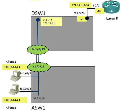
In this article we will discuss about the configuration on the switches of the TSHOOT Demo ticket. We post the topology here for your reference.
Layer2/3 topology

Main Configuration on DSW1 and ASW1
|
DSW1: ip routing |
ASW1: vtp mode transparent |
From the output above we learn that:
+ VTP is disabled on both switches.
+ DSW1: running EIGRP (Layer 3 switch) while ASW1 is pure layer 2 switch
+ Configuration VLANs on both switches as follows:
a) VLAN 10: CLIENT_VLAN (two computers are assigned to this VLAN)
b) VLAN 98: NATIVE_VLAN (no ports are assigned to this VLAN. This VLAN exists just to make sure traffic from other VLANs are tagged)
c) VLAN 99: PARKING_LOT (unused ports are assigned to this VLAN)
+ Fa1/0/19 is the trunking port between two switches
+ Only VLAN 10 and 98 are allowed to go through 2 switches.
+ Default gateway on two PCs are 172.16.2.1 which is the IP address of Interface VLAN 10 on DSW1.
+ EIGRP updated is only sent and received on fa1/0/1 which connects from DSW1 to R4
+ On ASW1, spanning-tree PortFast feature is enabled on fa1/0/1 & fa1/0/2 which are connected to two PCs.
Note: On DSW1, under interface Fa1/0/19 we can see this command:
switchport access vlan 99
but this port is set as trunk port (switchport mode trunk) so how can a command for access port be there? Well, in fact we have set this port to trunk mode so the switchport access vlan 99 command has no effect at all. It only affects when you change this port to an access port and this port would be assigned to VLAN 99.
The IP address of interface VLAN 10 (172.16.2.1/24) is set as the default gateway on Host 1 & Host 2. In general, a Switch Virtual Interface (SVI) represents a logical Layer 3 interface on a switch and it can be used to interconnect Layer 3 networks using routing protocols (like RIP, OSPF, EIGRP…). When packets reach this SVI, the Layer 3 switch will look up in its routing table to see if there is an entry to route the packets to the destination. In this case, packets sent from Host 1 & 2 reach 172.16.2.1 (because this IP is also the default gateway set on Host 1 & 2), then DSW1 looks up in its routing table for a suitable entry to the destination.
|
Quick reminder: VLAN interfaces or switched virtual interfaces (SVI) are logical layer 3 routable interface. Generally, SVIs are often used to accomplish InterVLAN routing on a Layer 3 switch. From there, you would point the client devices to the VLAN interface to use as it’s default gateway. When a packet arrives on that interface, the Layer 3 switch will do a routing table lookup and perform routing process like a normal packet. |
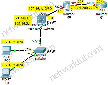
In the next part we will try to do above topology in Packet Tracer. But Packet Tracer does not understand redistribute static route into EIGRP so we simplify the configuration by running EIGRP on all routers.
Physical topology

Tasks in the lab:
+ VTP is disabled on both switches.
+ DSW1: running EIGRP (Layer 3 switch) while ASW1 is pure layer 2 switch
+ Configuration VLANs on both switches as follows:
a) VLAN 10: CLIENT_VLAN (two computers are assigned to this VLAN)
b) VLAN 98: NATIVE_VLAN (no ports are assigned to this VLAN. This VLAN exists just to make sure traffic from other VLANs are tagged)
c) VLAN 99: PARKING_LOT (unused ports are assigned to this VLAN)
+ Fa0/19 is the trunking port between two switches
+ Only VLAN 10 and 98 are allowed to go through 2 switches.
+ Default gateway on two PCs are 172.16.2.1 which is the IP address of Interface VLAN 10 on DSW1.
+ EIGRP updated is only sent and received on fa0/1 which connects from DSW1 to R4
+ On ASW1, spanning-tree PortFast feature is enabled on fa0/1 & fa0/2 which are connected to two PCs.
Configuration
| ASW1 hostname ASW1 ! vtp mode transparent ! vlan 10 name CLIENT_VLAN ! vlan 98 name NATIVE_VLAN ! vlan 99 name PARKING_LOT ! interface FastEthernet0/1 switchport access vlan 10 switchport mode access spanning-tree portfast ! interface FastEthernet0/2 switchport access vlan 10 switchport mode access spanning-tree portfast ! interface FastEthernet0/19 description Link to DSW1 switchport trunk encapsulation dot1q switchport trunk native vlan 98 switchport trunk allowed vlan 10,98 switchport mode trunk |
DSW1 hostname DSW1 ip routing ! vtp mode transparent ! vlan 10 name CLIENT_VLAN ! vlan 98 name NATIVE_VLAN ! vlan 99 name PARKING_LOT ! interface FastEthernet0/1 description Link to R4 no switchport ip address 172.16.1.14 255.255.255.252 no shutdown ! interface FastEthernet0/19 description Trunk to ASW1 switchport access vlan 99 switchport trunk encapsulation dot1q switchport trunk native vlan 98 switchport trunk allowed vlan 10,98 switchport mode trunk ! interface Vlan10 ip address 172.16.2.1 255.255.255.0 ! router eigrp 16 network 172.16.1.0 0.0.0.255 network 172.16.2.0 0.0.0.255 passive-interface default no passive-interface FastEthernet0/1 |
| R0 hostname R0 ! interface FastEthernet0/0 ip address 172.16.1.13 255.255.255.252 no shutdown ! interface FastEthernet0/1 ip address 209.65.200.225 255.255.255.252 no shutdown ! router eigrp 16 network 172.16.0.0 network 209.65.200.0 |
R1 hostname R1 ! interface FastEthernet0/0 ip address 209.65.200.226 255.255.255.252 no shutdown ! router eigrp 16 network 209.65.200.0 |
Also configure IP addresses and default gateways of the two computers as follows:
| PC0 IP: 172.16.2.3/24 Default gateway: 172.16.2.1 |
PC1 IP: 172.16.2.4/24 Default gateway: 172.16.2.1 |
Now two hosts can ping 209.65.200.226.
The Packet Tracer initial and final configs can be downloaded here:
Initial Configs: https://www.networktut.com/download/TSHOOT_demo_VLAN_switches_initial.zip
Final Configs: https://www.networktut.com/download/TSHOOT_demo_VLAN_switches_finalConfigs.zip


