Frame Relay Point-to-Point SubInterface GNS3 Lab
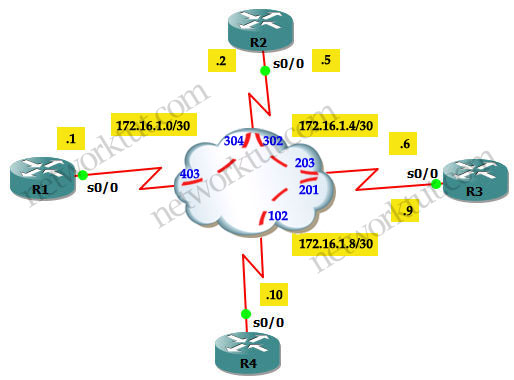
In this lab we will try to run a Frame Relay topology same as the one posted in TSHOOT demo ticket. The logical and physical topologies of this lab are shown below:
Logical topology:

Tasks in this lab:
+ Configure static mappings on R1 and R4.
+ Configure point-to-point subinterface on R2 & R3.
+ All routers must be able to ping themselves.
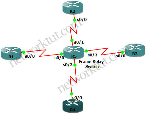
Physical topology:

IOS used in this lab: c3640-jk9s-mz.124-16.bin
We will use a router (R5) to simulate the Frame Relay switch instead of using a Frame Relay Switch in GNS3. First we will configure the Frame Relay switch with the DLCIs shown above. In fact the DLCIs in the topology are not very logical, especially DLCIs 304 & 403 for the links between R1 & R2, but well… let’s configure them.
Note: If you are not sure about Frame Relay theory, please read my Frame Relay tutorial first.
Configuration
Configure Frame Relay Switch:
We should change the name of R5 to FRSW (Frame Relay Switch).
R5(config)#hostname FRSW
The very first command to turn on the frame relay switching feature on FRSW:
FRSW(config)#frame-relay switching
| FRSW(config)#int s0/0 FRSW(config-if)#encapsulation frame-relay FRSW(config-if)#frame-relay intf-type dce FRSW(config-if)#clock rate 64000 FRSW(config-if)#frame-relay route 403 interface serial 0/1 304 FRSW(config-if)#no shutdown |
FRSW(config)#int s0/1 FRSW(config-if)#encapsulation frame-relay FRSW(config-if)#frame-relay intf-type dce FRSW(config-if)#clock rate 64000 FRSW(config-if)#frame-relay route 304 interface serial 0/0 403 FRSW(config-if)#frame-relay route 302 interface serial 0/2 203 FRSW(config-if)#no shutdown |
| FRSW(config)#int s0/2 FRSW(config-if)#encapsulation frame-relay FRSW(config-if)#frame-relay intf-type dce FRSW(config-if)#clock rate 64000 FRSW(config-if)#frame-relay route 203 interface serial 0/1 302 FRSW(config-if)#frame-relay route 201 interface serial 0/3 102 FRSW(config-if)#no shutdown |
FRSW(config)#int s0/3 |
+ The frame-relay intf-type dce command specifies the interface to handle LMI like a Frame Relay DCE device. This command also enables FRSW to function as a switch connected to a router. And the clock rate is necessary on the DCE end of the connection so we have to put it here (but in fact not all IOS versions require this, you can check or verify the DCE and clock rate with the show controller serial x/y command).
+ The frame-relay route 403 interface serial 0/1 304 command means frame-relay traffic comes to FRSW which has a DLCI of 403 will be sent to interface Serial0/1 with a DLCI of 304.
Also please notice that there is no IP address configured on the Frame Relay Switch.
We can verify the configuration of the FRSW with show frame-relay route command:

Note: The output above is taken after all routers have been configured so if you do this command in your lab at this moment the Status would be Inactive because you have not turned on the Serial interfaces on R1, R2, R3, R4.
Configure R1, R2, R3 and R4:
First I show all the configuration but you should type them manually to see how it works instead of pasting all of them at the same time.
| R1: interface s0/0 ip address 172.16.1.1 255.255.255.252 encapsulation frame-relay no frame-relay inverse-arp frame-relay map ip 172.16.1.1 403 broadcast frame-relay map ip 172.16.1.2 403 no shutdown (good to explain first broadcast: https://learningnetwork.cisco.com/thread/35698) |
R2: interface Serial0/0 no ip address encapsulation frame-relay no shutdown ! interface Serial0/0.12 point-to-point description Link to R1 ip address 172.16.1.2 255.255.255.252 frame-relay interface-dlci 304 ! interface Serial0/0.23 point-to-point description Link to R3 ip address 172.16.1.5 255.255.255.252 frame-relay interface-dlci 302 |
| R3: interface Serial0/0 no ip address encapsulation frame-relay no frame-relay inverse-arp no shutdown ! interface Serial0/0.23 point-to-point description Link to R2 ip address 172.16.1.6 255.255.255.252 frame-relay interface-dlci 203 ! interface Serial0/0.34 point-to-point description Link to R4 ip address 172.16.1.9 255.255.255.252 frame-relay interface-dlci 201 |
R4: interface Serial0/0 description Link to R3 ip address 172.16.1.10 255.255.255.252 encapsulation frame-relay frame-relay map ip 172.16.1.9 102 broadcast frame-relay map ip 172.16.1.10 102 no frame-relay inverse-arp no shutdown |
There are somethings I wish to explain. For example on R1 under interface s0/0 we see the command:
frame-relay map ip 172.16.1.1 403 broadcast
The frame-relay map command performs static addressing mapping and it disables Inverse ARP on the specified DLCI. This command is supported on the physical interface and it should be used when the far end Frame Relay device does not support Inverse ARP. If we choose to disable Inverse ARP, we must perform a static mapping of L2 to L3, as well as associate the DLCI to the interface.
The IP address 172.16.1.1 is the IP address of R1 itself so why do we need this command? The answer is: without this command, you cannot ping from R1 to itself (ping to it own IP address may be a lab requirement, a fun test…) because that IP address does not exist in the Frame Relay map table and Frame Relay does not know which DLCI it should use to send the frames to this destination. You can check this with the “debug frame-relay packet” command to see the error Serial0/0:Encaps failed–no map entry link 7(IP). By adding a static map to the DLCI used for a neighbor, when we ping to itself, the router will send ICMP to that neighbor and the neighbor will reply back to R1.
Now let’s discuss about the broadcast keyword in the above command. First, please notice that the “broadcast” keyword here is used for both multicast and broadcast traffic. By default, Frame Relay is a non-broadcast multiple access (NBMA) network and does not support broadcast or multicast traffic. So without the broadcast keyword, dynamic routing protocols such as EIGRP, OSPF and RIPv2 would not be able to advertise multicast route updates over the corresponding DLCI. Therefore we should always add this keyword in the “frame-relay map” command. But remember this: we only use one broadcast keyword for each DLCI regardless how many IP addresses are used along with. So the commands below:
frame-relay map ip 172.16.1.1 403 broadcast
frame-relay map ip 172.16.1.2 403
are same as:
frame-relay map ip 172.16.1.1 403
frame-relay map ip 172.16.1.2 403 broadcast
You should never use more then one broadcast keyword for one DLCI like this:
frame-relay map ip 172.16.1.1 403 broadcast
frame-relay map ip 172.16.1.2 403 broadcast
or you will end up with multiple copies of the packets being transported and received.
Configuring static map statements (like frame-relay map ip command) automatically disables Inverse ARP so in the configuration of R1, the no frame-relay inverse-arp command is in fact not necessary.
Note: Physical interfaces have Inverse ARP enabled by default
That is all explanation for R1. Next we will discuss about the configuration of R2 and R3 (they are very identical). Under subinterface (like Serial0/0.12 point-to-point on R2) we see the command:
frame-relay interface-dlci 304
We notice that in this command only the DLCI is specified and this command just associates the DLCI with the subinterface. This is because point-to-point network only connects with one remote destination. Therefore this command is mostly used under point-to-point subinterface (but it can be still used on physical interface although it has no effect because all unassigned DLCIs belong to that physical interface by default). On point-to-point subinterface, Inverse ARP requests are not sent out regardless if it is enabled on the physical interface or not. It is also not required to enable or disable Inverse ARP, because there is only a single remote destination on a PVC and discovery is not necessary. Also notice that the frame-relay map command is not allowed on a point-to-point subinterface.
Note: Using subinterface can avoid the split-horizon problem.
We can check which type of mapping was configured with the command “show frame-relay map”:
+ Dynamic means the mapping was done using Inverse ARP.
+ Static means the mapping was done manually.
For example on R1 static mapping is being used:

Let’s check R2:

Hmm, on R2 we don’t see the word “static” or “dynamic”. There are some confusions about the “frame-relay interface-dlci” command if it belongs to dynamic mapping or static mapping. But there is an opinion saying that point-to-point does not use the principle of static or dynamic mapping so it is not listed here. Well, the decision is yours.
Also you can notice that no Layer 3 addresses are shown in above command.
On the “show frame-relay map” outputs above you can see the Frame Relay’s statuses are all active. There are 4 PVC statuses:
+ Active: Both sides of the PVC are up and communicating.
+ Inactive: Local router received status about the DLCI from the frame-switch, the other side is down.
+ Deleted: Indicates a local config problem. The frame-switch has no such mapping and responded with a “deleted message”.
+ Static: Indicates that LMI was turned off with the “no keepalives”.
The outputs of the show frame-relay map command on R3 & R4 are very identical to R1 & R2, I also post here just for your reference:


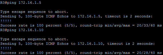
That’s all I wish to explain, let’s check if the pings work…


So all the pings to the neighbors are working. On R1 you can try pinging itself and it will successful too. If you disable the frame-relay map ip 172.16.1.1 403 broadcast command (use no frame-relay map ip 172.16.1.1 403 broadcast), R1 cannot ping itself anymore:

In this Frame Relay lab we only set path for adjacent routers. We can’t ping between R1 to R3 for example. There are two solutions so that R1 can ping R3:
+ Use multipoint subinterfaces on R2 (disable Inverse ARP and set two static frame-relay mappings on both R1 and R3)
+ Enable a routing protocol (static routing, EIGRP, OSPF, RIP…)
The GNS3 initial and final configs can be downloaded here:
Initial Configs:https://www.networktut.com/download/Frame_Relay_TSHOOT_demo_initial.zip
Final Configs: https://www.networktut.com/download/Frame_Relay_TSHOOT_demo_finalConfigs.zip
————————————————————————————————————————————-
Some good references:
http://www.ciscopress.com/articles/article.asp?p=170741&seqNum=6
http://www.cisco.com/en/US/tech/tk713/tk237/technologies_q_and_a_item09186a008009457a.shtml
http://www.cisco.com/en/US/tech/tk713/tk237/technologies_tech_note09186a008014f8a7.shtml
Next recommended reading: EIGRP over Frame Relay and EIGRP Redistribute Lab


I am so confused… which part is the question?